
Status after the first year (WP3)
Results September 2012 to October 2013
The winter of 2012 and spring of 2013 saw an intensive development of the vibracoring device carred out by AKUT, with preliminary field testing in collaboration with the National Museum of Denmark. At the same time Unisense began work on developing the data logging systems. Shortly after the start of the project it was decided that two separate systems should be developed to best achieve the desired results of measuring and logging environmental parameters in both the open water and sediments. These were to be based on existing systems within the Unisense range of products, yet entailed considerable re-development and integration of new software and hardware. The various equipment designed was trialled in earnest in the Summer of 2013 on the site of Tudse Hage in order to get a first impression of the applicability of the first concept devices.
Vibracoring System
The specifications for the vibracoring system were such that it should:
- be able to take samples down to a depth of 50 cm in the seabed
- be diver held and ideally operated by one diver only
- be easy to pass/vibrate into the bottom and easy to retrieve
- be able to preserve the core with a suitable sediment retainer
- ensure best possible preservation of the core, in order to take gas measurements and pore water analysis through sealed holes in the coring tube
In general the system should improve upon currently available corer systems in terms of diver deployment, retrieval and ease of analysis of samples. The resultant system based on the above criteria consists of the following:
- 80 mm diameter polycarbonate tube for collecting the sediment samples although smaller tube sizes can be relatively easily adapted
- An interchangeable vibrator head
- A pneumatic vibrator providing longitudinal vibrations
- A spring connecting vibrator with weight
- Weight system for creating downward force on vibrator and coring tube
- A lifting bag connected to the weight for balancing the unit
- A “handle bar” with operating valve
- An exhaust system with buoyancy
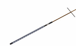
The vital part of the corer is the vibrator. A pneumatic driven unit was selected, as divers are familiar with compressed air and because compressed air is available in connection with diving activities. The unit can be supplied by an umbilical cord from the surface or from tanks at the bottom depending on numbers of samples to be made, working depth, and the facilities of the supporting dive vessels.
The coring tube is made of transparent polycarbonate. The tube has a simple system for attachment to the vibrator head and for allowing water to escape the coring tube during penetration. Both systems can easily be operated by divers even with gloves. The coring tube is mounted on the vibrator by an interchangeable head, in order to be able to use tubes of different diameters. The head also makes changing of coring tubes under water simple. The downward force on the tube is achieved by a weight with a diver held “handle bar” connected to the vibrator through a spring. The spring protects the diver from the vibrations and insures that all vibration energy is channelled to the coring tube. The weight system is connected to a lifting bag, making it possible to adjust the downward force by regulating the amount of air in the bag. The lifting bag can be filled by exhaust air from the vibrator and provides upward force to ease the retrieving of the core from the seabed.


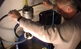
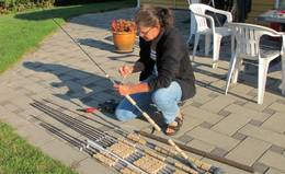
- Figure 1. Photo: AKUT

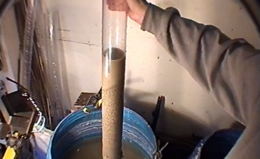
- The AKUT vibracorer on test in an artificial seabed and dry soil.

Datalogging Systems
Open water
The open water data logging system was to be based on the lander technologies that Unisense have currently developed. The parameters to be measured were standard CTD data (conductivity (salinity), temperature and depth data) and an Acoustic Doppler Current Profiler (ADCP water current meter). Integration of these instruments and modification of hardware, software and firm ware took place over the Winter of 2012 – 2013 ready for an initial trial on the site of Tudse Hage in the Summer of 2013.
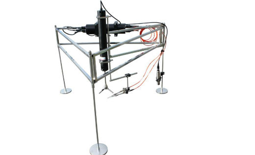
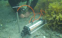
- Figure 2: Mark I of the openwater data logger. Photo: Unisense
Sediment profiling system
It was desired to measure sediment profiles in situ using a diver based datalogging system down to a depth of 50 cm. An existing diver operated underwater meter manufactured by Unisense was re-developed for this purpose. The standard equipment has the capability of measuring dissolved oxygen, pH, redox and sulphide using Unisense’s microsensors that are fitted with hypodermic needles to give them added robustness. However, this system was developed for measuring in the upper few centimetres of sediments; not profiling down to 50 cms depth. As with the open water data logger extensive development of the existing equipment and a “spear” system, which could be pressed into the sediment was developed. This again required re-configuration of the hardware, software and firmware of the existing underwater meter and the re-design of sensors to fit into the spear system which would be relatively easily operable by a diver underwater. The concept was to make a hollow spear which could be hammered into the sediment to the desired depth and then the sensors placed into this to take the desired measurements.
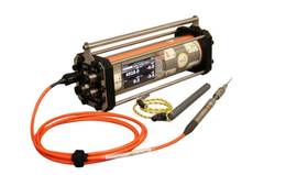
- Figure 3: Unisense standard underwater meter. Photo: Unisense

- Figure 4: Spear device for sediment profiling down to 50cm. Photo: Unisense

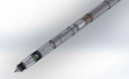
- Figure 5: Schematic diagram of the working end of the spear with a sensor in position. Photo: Unisense

Field work, Tudsehage, Denmark
Preliminary Field Testing in Tudse Hage August 2013
At the end of August all equipment was ready for the first serious field trials on the site of Tudse Hage. The team consisted of partners from the National Museum of Denmark, the Viking Ship Museum, AKUT, Unisense and the University of Gothenburg. Field work took place over two weeks with the first week dedicated to localisation and preparation of suitable areas for testing and monitoring of the artificial sea grass mats (see section on WP6 in situ preservation). The second week was trialling of the various systems developed. Following kind permission from the Danish Cultural Heritage Agency it was agreed that there could be minimal intervention on the site in order to trial the equipment and take sediment, wood samples and place modern wood into the site. The vibracoring system was to be used in order to obtain cores for further analysis in the field and laboratory. Profiles of the aforementioned parameters were to be measured in the cores in the field in order to compare these results with in situ profiles measured using the in situ spear /sediment profiler so as to compare and validate both methods. The open water data logger was trialled around one of the artificial sea grass mats to see if differences in current strength and direction around the mat could be determined. Samples of archaeological wood were also taken from the various layers of the site in order to examine their state of preservation, which could be compared with the environmental parameters measured in the cores and with the in situ profiling equipment. Similarly, modern samples of wood were placed into the site so that their deterioration processes could be examined over time.
Testing of the open water datalogger
In connection with the trialling of the artificial seagrass the open water datalogger was to be placed on one of the mats near Tudse Hage. The idea was to log data over two days on the shoreward side of the mat and then move it to the off shore side. The hypothesis being that there may be more current on the off shore side due to the greater fetch from the Great Belt and in this way it may be possible to see if the seagrass was actually reducing any eventual currents and thus prevent any resultant scouring of sediment. The logger was assembled in the harbour of Skælskør and transported onto site using a small vessel (6.2 metres). Although relatively large and heavy the logger was easily lowered by two people onto the seabed (Figure 6). A single diver was then able to position it in the correct orientation on the seabed and on the onshore side of the mat. Following logging for two days the logger was moved to the opposite side of the seagrass mat (off shore), using a diver on the seabed and support on the surface. CTD and current data were successfully collected and are currently undergoing post processing. The system will be trialled further in the coming year of the project.
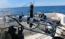
- Figure 6: The Unisense openwater data logger ready for deployment.
- Figure 7: The logger on the on shore side of the seagrass mat (the mat can be seen in the back ground)
Environmental Measurement in Marine Sediments Using a Datalogger, Denmark
Open Water Datalogger
The test area in Tudse Hage
A 1 × 1 metre test pit which had been previously excavated and re-buried as part of the Viking Ship Museum’s investigations on the site between 2009 – 11 was selected as the test area (Figure 8).
This pit had yielded a ca 50 cm profile of sand / gravel and organic gytjja with numerous fragments of wood (both worked and natural) overlying the natural clay and provided the perfect area to test the vibracorer and in situ spear / profiler.
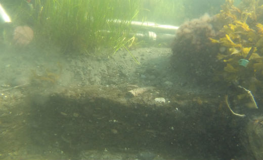
- Figure 8: Test pit area where the vibracorer and in situ spear / profiler were trialled and where wood samples were taken for analysis. Photo National Museum of Denmark.

The Vibracoring system
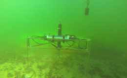
The Vibracorer was used to take sediment cores from around the edge of the test pit. Locations ca 50 cm from the edge of the pit were selected and three cores from the southern, eastern and western edge taken. The shallow water of the site (ca. 2 metres) made working with the system slightly challenging as the weight of the device is designed to be supported by lifting bags (Figure 9).
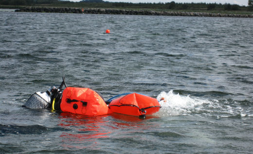
- Figure 9: Vibracorer in use as seen from the surface. The lifting bags are designed to both support the vibracorer and make it easier for divers to remove the sediment cores.

Nevertheless, the cores were quickly taken (ca. 10 minutes per core) (Figure 10) and the experience of working on an actual site and in shallow water gave rise to numerous improvements to the system, which will be worked on in the coming months.
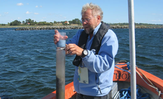
- Figure 10: Dr Poul Jensen from AKUT labelling a sediment core. Photo National Museum of Denmark

The cores were taken back on land and profiles of dissolved oxygen, pH, redox potential and sulphide were taken using Unisense’s standard laboratory sensors (Figure 11).
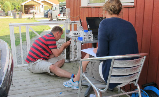
- Figure 11: Dr Mikkel Holmen Andersen (Unisense) and Anne Marie Eriksen (National Museum of Denmark) measuring sediment profile parameters in the cores.

Sediment Corer, Denmark
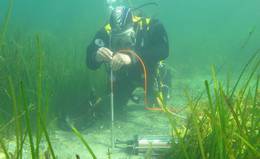
In situ spear / sediment profiler
Measurement of environmental parameters within cores, either using microsensors or from extracted pore water, is currently the most frequently used method for analysing environmental parameters within sediment. However, it is advantageous if these parameters could also be measured in situ. The in situ profiler system was trialled in two areas adjacent to where the cores had been taken in order to compare and contrast the methods and in this way validate both methods. In this instance only sulphide microsensors were used as the main aim of this trial was to test the use of the equipment. The first impressions of the system were such that the meter in itself was extremely simple to use with commands and data being logged using magnetic keys controlled by a “wand” from outside the underwater housing. The spear itself was easy in this instance to simply press/hammer into the sediment, although it has also been pressed into more compacted sediments in another trial using the vibracoring device. It was important to ensure sand did not get into the open end of the spear as this collected above the rubber septum and could damage the microsensor as it was passed into the spear. In this way measurements were taken every 5 cm down to a depth of ca. 50 cm.
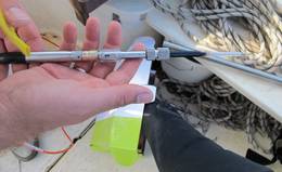
- Figure 12: The microsensor with hypodermic needle which is passed into the metal spear and passes through the septum into the sediment. Photo: The Viking Ship Museum

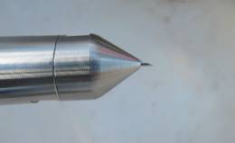
- Figure 13: End of the spear with the hypodermic needle of the microsensor passing through. Photo: The Viking Ship Museum

- Figure 14: Inserting the microsensor into the spear. Photo: Viking Ship Museum.

- Figure 15: Waiting for the sensor to stabilise. Photo: Viking Ship Museum.

Wood Deterioration
To supplement the environmental monitoring aspects of the project wood samples were taken from the discrete layers of the test pit; wood overlying the natural clay substrate; wood within the gyttja, wood overlying the gyttja and below the mobile sand / gravel layer and also currently exposed lying on the seabed. Dr Charlotte Björdal of the University of Gothenburg is currently assessing these samples with the aid of microscopic techniques in order to look at the state of preservation of the wood and importantly ascertain what organisms have caused the deterioration. This will be correlated with the results of the environmental monitoring and future laboratory microcosm tests to look at the turnover of organic archaeological materials in waterlogged environments.
- Figure 16: Dr Charlotte Björdal from the University of Gothenburg preparing modern wood samples.

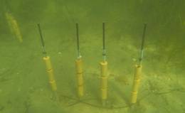
- Figure 17: Modern wood samples in situ. On each kebab there are two sets of samples that are buried within the sediment and one set of samples exposed to the open seawater as a negative control.

In order to gain more information on the actual deterioration of wood a series of modern pine samples were placed on site using a “kebab” system (Figure 17). This entailed threading small cylinders of fresh pine wood onto a carbon fibre rod at different depths down to ca 50 cm, with a spear mounted on the end and pressing them into the site using the vibracoring system. These samples will be examined over the life time of the project and it is hoped in the future to better understand the deterioration and preservation of wood in waterlogged / marine environments.
- Figure 18A: Dr Charlotte Björdal from the University of Gothenburg preparing modern wood samples (A). Photo: University of Gothenburg.

- Figure 18B: On each kebab there are two sets of samples that are buried within the sediment and one set of samples exposed to the open seawater as a negative control. (B). Photo: University of Gothenburg.

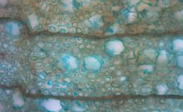
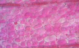
The above photos:
Micrographs showing a cross section of hazel (Corylus sp.) with total decay of the secondary cell wall. Degradation is caused by erosion bacteria known to degrade wood in low oxygen environments. The secondary cell wall is transformed to a residual material detached from the compound middle lamella visualized as a loose material in the lumen. Remaining skeleton / network that provides the wood its physical integrity is the lignin rich middle lamella. The wood sample (a tiny branch) was found in the upper layer of the sediment at Tudse Hage.
Assessing the Deterioration of Wood, Denmark
Future work
Following the successful preliminary trials of the various concept devices much has been learned. Refinements of the equipment will be made over the Winter in preparation for further trials on the sites in the project when final proofs of concept are ready. The sediment cores taken from the site will undergo further analysis and in particular be incorporated in a series of in vitro microcosm studies whereby the rates of turnover of organic material and wood deterioration in particular in different sediment types will be examined under controlled conditions in the laboratory. The results of all these developments and the implications of the results in terms of the assessment of the marine environment and sediments on the preservation of archaeological materials will be synthesised into the Guidelines to be prepared towards the end of the project in 2015.
David Gregory, Anne Marie Eriksen, Mikkel Holmen Andersen, Robert Fløng Pedersen, Poul Jensen and Charlotte Björdal